OSPF Configuration In Packet Tracer:
This article is about the “OSPF Configuration In Packet Tracer”. I will give you a basic overview of OSPF and then will provide the details of these configurations by practically configuring a lab. With the Basic overview of OSPF configuration, you can learn, how to configure OSPF on any cisco device this will provide you the basic steps for understanding OSPF configurations.
Related: Complete Cisco Router Configuration for beginners
OSPF Configurations Steps:
Configuration of OSPF is super Easy and very simple. As compared to any other routing protocols like RIP, EIGRP you are required the following basic steps to enable OSPF on a router.
- Enable OSPF on Router by using command ospf PROCESS-ID
- Define the interfaces on which you want to advertise in OSPF, you can do this with network IP_ADDRESS WILDCARD_MASK AREA_ID or IP OSPF command at the interface level.
- Define Router ID (An advance concept not related to this article)
For easy understanding of OSPF Configurations we have divided this article into two parts:
-
- Single Area OSPF Configuration
- OSPF Multi-Area Configuration
OSPF Single Area configuration In Packet Tracer:
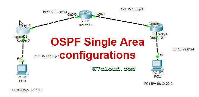
This OSPF lab is created in packet tracer and you will learn the OSPF single area configuration from this lab. OSPF is an open standard protocol, you learn more why we use OSPF and OSPF Quiz from here. This is a basic labs regarding OSPF single area configure related to CCNA or ICND1/2 exam. In the following figure there are the three routers with the following specification or required configurations:
| Device Name | Protocol configuration | IP Scheme / Interface configurations |
| PC0 | — | F0 = 192.168.44.2\24 |
| PC1 | — | F0 = 10.10.22.2\24 |
| Router0 | OSPF 1 | G0/0 = 192.168.44.1\24, G0/1 = 192.168.55.1\24 |
| Router1 | OSPF 1 | G0/0 = 192.168.55.2\24, G0/1 = 172.16.10.1\24 |
| Router2 | OSPF 1 | G0/0 = 172.16.10.2\24, G0/1 = 10.10.22.1\24 |
Lab Objective
• Setup an IP addressing scheme on all the devices according to above table.
• Configure and verify Open Shortest Path First (OSPF) routing.
Solution:
Configure and create the above lab in packet tracer and complete the IP configuration with following configurations:
Router0 IP and interface Configuration:
On the router, enter the global configuration mode and configure the hostname as shown in the chart. Then configure the console, virtual terminal and enable passwords. Next configure the interfaces according to the chart.
Router>enable
Router#conf t
Router(config)#hostname Router0
Router0(config)#interface gigabitEthernet 0/0
Router0(config-if)#ip address 192.168.44.1 255.255.255.0
Router0(config-if)#no shut
Router0(config-if)#exit
Router0(config)#interface gigabitEthernet 0/1
Router0(config-if)#ip address 192.168.55.1 255.255.255.0
Router0(config-if)#no shutdown
Router1 IP Configuration:
Perform the same configuration as on above router with their IP scheme.
Router>enable
Router#conf t
Router(config)#hostname Router1
Router1(config)#interface gigabitEthernet 0/0
Router1(config-if)#ip address 192.168.55.2 255.255.255.0
Router1(config-if)#no shut
Router1(config-if)#exi
Router1(config)#interface gigabitEthernet 0/1
Router1(config-if)#ip address 172.16.10.1 255.255.255.0
Router1(config-if)#no shutdown
Router2 IP and interface Configuration:
Router>enable
Router#conf t
Router(config)#hostname Router2
Router2(config)#int gigabitEthernet 0/0
Router2(config-if)#ip address 172.16.10.2 255.255.255.0
Router2(config-if)#no shut
Router2(config-if)#exit
Router2(config)#interface gigabitEthernet 0/1
Router2(config-if)#ip address 10.10.22.1 255.255.255.0
Router2(config-if)#no shutdown
PC0 Configuration:
Assign the IP address, subnet mask, and gateway. 255.255.255.0 is the Subnet mask and gateway will be the next hope address of the router or the IP of router-interface attached with PC, and in this case, it is 192.168.44.1. Each workstation should be able to ping the attached router.
PC1 Configuration:
Configure this workstation with the following IPs:
IP address: 10.10.22.2
Subnet Mask: 255.255.255.0
Gateway: 10.10.22.1
Task2 Configure and verify Open Shortest Path First (OSPF) routing:
Configure an OSPF routing process on all routers. Use OSPF process number 1 and ensure all networks are in area 0. For configuring any router with OSPF you need to advertise all the directly connected networks in the OSPF process. For example, on router0 you have the networks 192.168.44.0/24 and 192.168.55.0/24 so you can see that I have advertised these networks in area 0 for OSPF configurations.
Router0 OSPF Configuration:
Router0#conf t
Router0(config)#router ospf 1
Router0(config-router)#network 192.168.44.0 0.0.0.255 area 0
Router0(config-router)#network 192.168.55.0 0.0.0.255 area 0
Router0(config-router)#exit
Router1 OSPF Configuration:
Router1#conf t
Router1(config)#router ospf 1
Router1(config-router)#network 192.168.55.2 0.0.0.255 area 0
Router1(config-router)#network 172.16.10.0 0.0.0.255 area 0
Router1(config-router)#exit
Router2 OSPF Configuration:
Router2#conf t
Router2(config)#router ospf 1
Router2(config-router)#network 172.16.10.0 0.0.0.255 area 0
Router2(config-router)#network 10.10.22.0 0.0.0.255 area 0
Router2(config-router)#exit
Note: You can use the “ip OSPF area 0” command for configuring OSPF. For this you have entered the interface mode and then run the commands in the following way. for router2 you can use these commands:
Router2>en
Router2#conf t
Router2(config)#inter gigabitEthernet 0/0
Router2(config-if)#ip ospf area 0
Router2(config)#inter gigabitEthernet 0/1
Router2(config-if)#ip ospf area 0
But you are required the newer version of IOS for configuring these commands.
Testing for correct configuration:
You can ensure the correct configuration by following two ways:
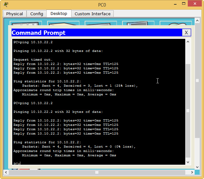
1. end to end ping should be successful, this means ping from PC0 to PC1 and vice versa should be successful. you can see the following image, we will have the same results in the case of correct configurations.
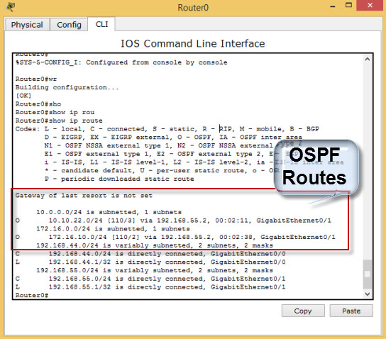
2. Show ip route command will display all the OSPF routes (including the networks which are not connected to router). Screenshot of “Show ip route” on Router0 will have the following output in case of correct configurations.
OSPF Mutli-Area Configuration
Like basic OSPF single area configuration, multi-area OSPF configuration is also simple. See the following multi-area OSPF topology:
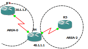
In this example, we have two OSPF areas that is area 0 and area 2. According to the network diagram, router R3 is in area 0. Router4 connects to both areas is area 0 and area 2, which makes him an Area Border Router, while router5 is in area 2. Router R3 and R5 configurations are the same as we learn in the above single area configuration lab. But configurations of router R4 is as follows:
R4#conf t
R4(config)#router ospf 1
R4(config-router)#network 30.1.1.0 0.0.0.255 area 0
R4(config-router)#network 40.1.1.0 0.0.0.255 area 2
R4(config-router)#router-id 4.4.4.4